A sequence diagram is an interaction diagram type, because it describes how a group of objects works together. Interaction diagrams are used to represent how the objects in the system connect and communicate with each other.
These diagrams provide us the context of an interaction between one or more lifelines in the system. This allows the specification of simple runtime scenarios in a graphical manner.
Sequence diagrams are also called event diagrams or event scenarios. Usually, these diagrams are used by business professionals and software developers to document processes or to understand requirements for a new system.
When to use Sequence Diagram
There are scenarios where the sequence diagram is the best UML to use:
- Usage scenario: a usage scenario is a diagram of how a system could potentially be used. It’s a great way to make sure you’ve worked through the logic of every possible scenario for the system.
- Service logic: if a service is used by different clients, a sequence diagram is an ideal way to map it out.
- Method logic: just as you might use the sequence diagram to explore the logic of a use case, you can use it to explore the logic of any function, procedure, or complex process.
Basic simbols and components
Sequence diagrams are made up of the following icons and elements:
- Object symbol: it represents a class or object in UML. The object symbol demonstrates how an object will behave in the context of the system. Class attributes shouldn’t be listed in this shape.

- Activation box: it represents the time needed for an object to complete a task. The longer the task will take, the longer the activation box becomes.

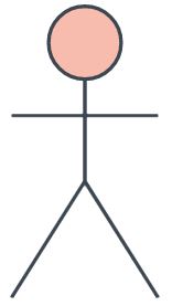
- Actor symbol: it shows entities that interact with or are external to the system.
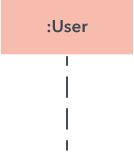
- Lifeline symbol: it represents the passage of time as it extends downward. The dashed vertical line shows the sequential events that occur to an object during the charted process. Lifelines may begin with a labelled rectangle shape or an actor symbol.
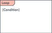
- Option loop symbol: it is used to model if/then scenarios. For example, a circumstance that will only occur under certain conditions.
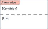
- Alternative symbol: it symbolizes a choice between two or more message sequences.
Common message symbols
The following arrows and message symbols are used to show how information is transmitted between objects. These symbols may reflect the start and execution of an operation or the sending and reception of a signal.
- Synchronous message symbol: it is represented by a solid line with a solid arrowhead. This symbol is used when a sender must wait for a response to a message before it continues. The diagram should show both the call and the reply.

- Asynchronous message symbol: it is represented by a solid line with a lined arrowhead. Asynchronous messages don’t require a response before the sender continues. Only the call should be included in the diagram.

- Asynchronous return message symbol: it is represented by a dashed line with a lined arrowhead.

- Asynchronous create message symbol: it is represented by a dashed line with a lined arrowhead. This message creates a new object.

- Reply message symbol: it is represented by a dashed line with a lined arrowhead.

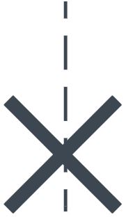
- Delete message symbol: it is represented by a solid line with a solid arrowhead, followed by an X. This message destroys an object.
Example in real life
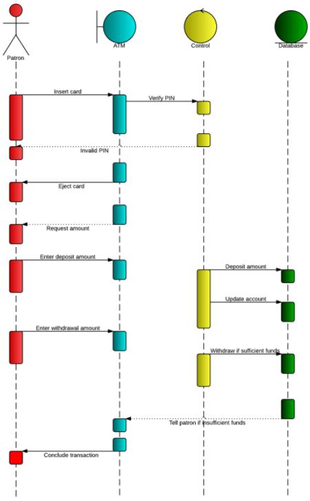
Here is an example of sequence diagram use for ATM systems.
An ATM allows people to access their bank accounts through a completely automated process. The example below outlines the sequential order of the interact ions in the ATM system.
